

Basic Background On Oscilloscopes:
Their Challenges In Field Work And A Better Solution
The Oscilloscope is one of the most common pieces of test equipment that an electronics technician or engineer uses. The Oscilloscope (referred to as a Scope) historically did one thing. It allowed the operator to see how the voltage level of the electronic circuit it was connected to changed over time. Generally for an electronic circuit to do something useful, the voltages in the circuit need to change. Think of an audio amplifier, for the amplifier circuit to do its job, which is to make a small input signal voltage into an identical, larger and more powerful output signal, voltages in the amp circuit need to change in response to the input signal’s changes. It is a huge benefit for engineers and technicians to be able to see how the circuit voltages change over time. Skilled practitioners can readily determine if something is wrong simply by seeing the circuit voltages.
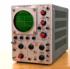 Scopes have been around for a long time and have evolved along the way. Originally it was a large and heavy tube based device that required a wheeled cart to move it around. It had a small, monochrome CRT tube, like what was used in televisions before the LCD. The screen showed a sharply drawn trace of the circuit voltage
 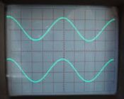 changing over time. The operator could view between 1 and 4 signals at the same time on the CRT depending on the sophistication of the scope. The height of the trace could be increased or decreased to fit it on the screen vertically and the horizontal time divisions could be made faster or slower to stretch out or contract the trace in time.
Over the past 80 years or so scopes have evolved into a much smaller and lighter piece of test equipment. As is typical of many types of electronics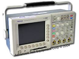 products, their performance and capabilities improved vastly while their costs dropped considerably. This bench style scope at right is just a fraction of the size and weight of the scope above yet is far more capable.
Most scopes are designed for use on a technician’s workbench but there are a number of scopes designed for handheld operation.
These handheld devices are particularly aimed at the field technician market. 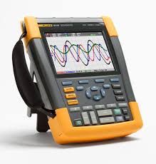 Field techs face a unique set of challenges. Often the environment that field techs work in are much harsher than engineers and technicians working in a corporate laboratory. The equipment under test can be located in an area that is uncomfortably hot, cold, cramped, high, etcetera. Often it is in an area that’s difficult to access and where it is hard to connect and operate equipment.
Many field service situations require personnel to wear various types of safety equipment ranging from fall arresting harnesses to cumbersome arc-flash 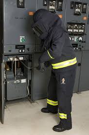 suits. The protection equipment can make carrying and operating a scope very difficult. Consider an arc flash suit that protects personnel working near high voltage power distribution systems from a lighting-like electrical arc that may flash out of electrical switch gear during operation. The burden of wearing such a suit, in areas that are often hot, is clear from the image at right. The gloves alone make operating the fine controls on a scope nearly impossible and removing them puts the operator at risk of severely burning his hands should an arc event occur.
This is only one example of the types of physical challenges confronting field technicians in the course of their work. Many are less life threatening but still make the operation and transportation of even handheld scopes less than convenient.
Inherent Problems With Current Scope Designs For Field Technicians
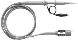 Even as scopes have gotten smaller and lighter their design still requires the operator to work very near the circuit he is probing. This is because the display, the controls and the input to the scope are all contained in the same box. The test probes that are used to connect the scope to the circuit under test are normally 1-meter (approx. 3 feet) long.
This is an example of a scope probe. One end has a connector for the scope and the other has a long, thin probe for connecting onto circuit component wires.
Because the probes are not very long, the scope and the operator need to be near the circuit being checked. Longer wires can be connected, but there are measurement tradeoffs that arise as the probe wires are made longer. These long wire issues can introduce inaccuracies and distortions in the trace being viewed and lead technicians to make incorrect conclusions about what is happening in the circuit under test. Long wires also create physical issues, like tripping hazards, in areas that may have considerable human traffic. This requires the technician to dress the wire in various ways to reduce the tripping hazard and that takes time both when setting up and when tearing down the test gear.
To date there have not been any really good oscilloscope solutions that address the myriad issues facing field technicians.
A Solution Developed For Field Techs
The way to address the short comings of typical scopes for field service work is to break the display and user controls which make up the User Interface (UI), the part of the scope that the user needs to interact with, from the scope’s inputs which need no user interaction once the connections to the circuit are made.
The AirScope from SavvyToad does just this. It is a compact device to which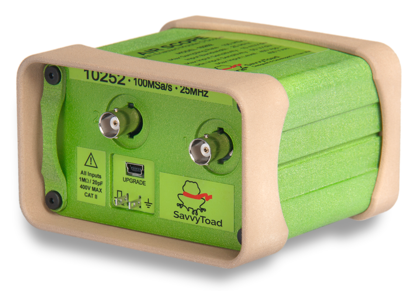 the scope probes are connected and stays near the circuit under test. It connects through a high-speed WiFi link to a mobile device, such as an iPad. The iPad contains a high resolution screen for viewing and touch controls for adjusting and measuring the signals being observed.
With an AirScope, a tech working on switch gear can get into a dangerous area when it is de-energized and safe, hook up the AirScope and then promptly exit the area. Now from a safe distance he can adjust the AirScope to show what is happening in the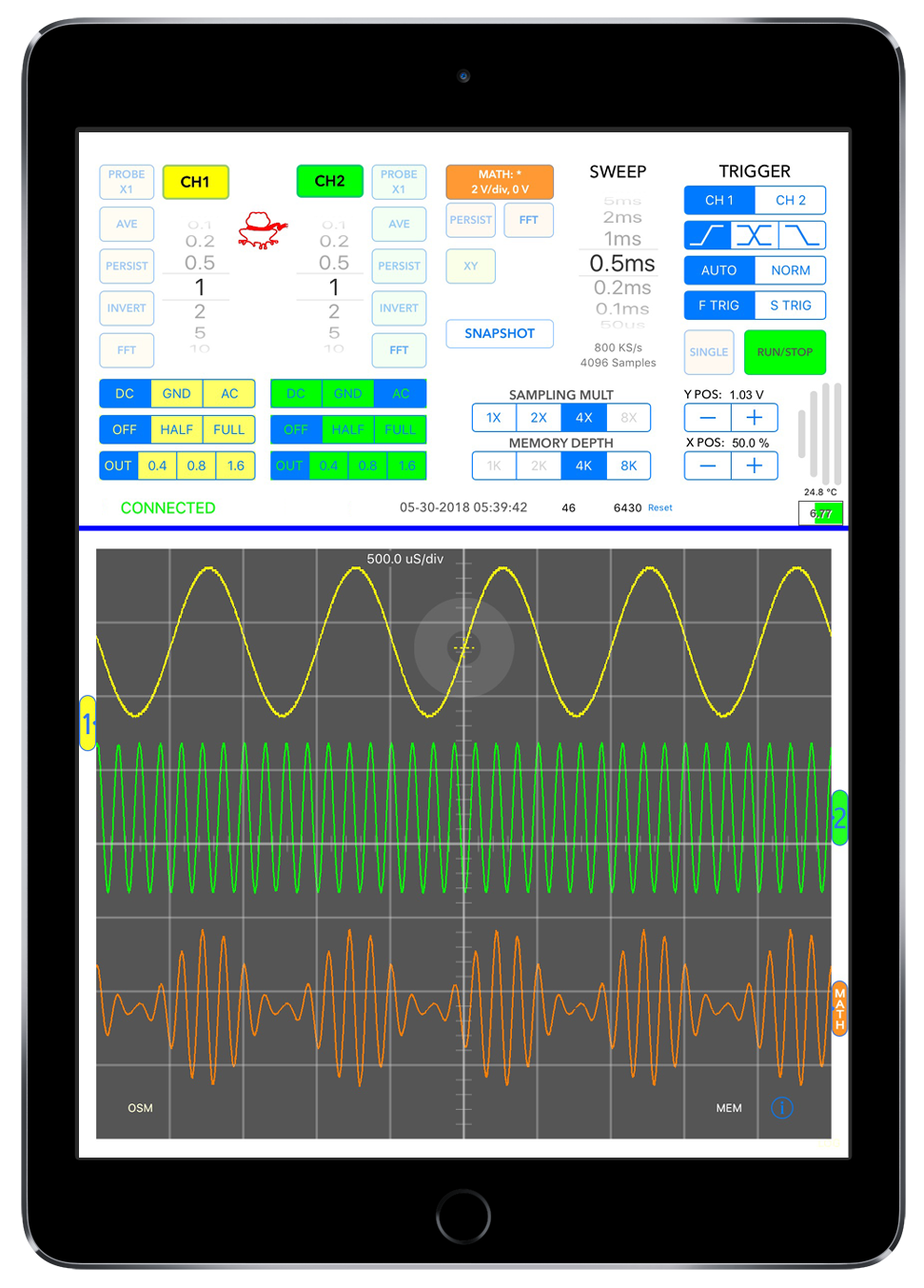 energized circuit. The standard 1-meter scope probes are used and since he is outside of the danger zone, he can operate the User Interface (UI) without the cumbersome arc flash gloves that would make operating a typical scope quite difficult.
Many times the controls for the circuit under test are not near the target circuits. Control rooms are usually located remotely from the devices they control. Freeing the User Interface (UI) from the probe inputs now allows it to be conveniently located by the controls for the circuit being monitored. Technicians can then make changes to the device controls and immediately see the effects of those adjustments on the circuit under test.
The AirScope links to the iPad using WiFi. The AirScope and the iPad communicate directly with each other in a peer-to-peer mode. This mode allows for quick link ups. There is no need to get IP addresses or passwords for a facility’s network.